HS3602 ICSJ010A Arduino Wireless Proto Shield
Wireless SD Shield for Arduino Xbee Module SD Card Socket
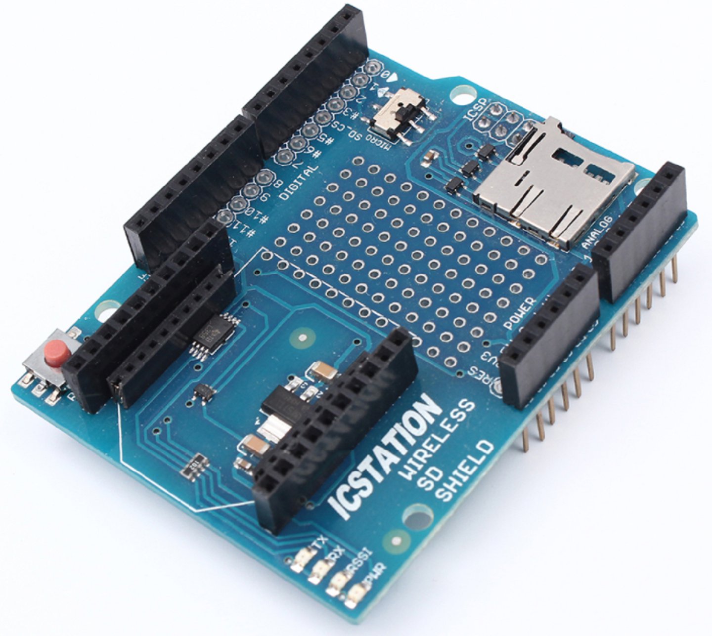
Description
The Wireless SD shield allows an board to communicate wirelessly using a wireless module. It is based on the Xbee modules from Digi , but can use any module with the same footprint. The module can communicate up to 100 feet indoors or 300 feet outdoors (with line-of-sight). It can be used as a serial/usb replacement or you can put it into a command mode and configure it for a variety of broadcast and mesh networking options. The shields breaks out each of the Xbee's pins to a through-hole solder pad. Included on board is a SD card slot. When using the SD Library to access the card, Pin 4 is CS and cannot be used otherwise. SPI also relies on pins 11, 12, and 13 for communication. An on-board switch allows the wireless module to communicate with the USB-to-serial converter or with the microntroller.
Switch Settings
The Wireless SD shield has an on-board switch labelled Serial Select. It determines how the Xbee's serial communication connects to the serial communication between the microcontroller (ATmega8 or ATmega168) and USB-to-serial chip on the board. When in the Micro position, the DOUT pin of the wireless module is connected to the RX pin of the microcontroller; and DIN is connected to TX. The wireless module will then communicate with the microcontroller. Note that the RX and TX pins of the microcontroller are still connected to the TX and RX pins (respectively) of the USB-to-serial converter. Data sent from the microcontroller will be transmitted to the computer via USB as well as being sent wirelessly by the wireless module. The microcontroller will not be programmable via USB in this mode.
With the switch in the USB position, the DOUT pin the wireless module is connected to the RX pin of the USB-to-serial converter, and DIN on the wireless module is connected to the TX pin of the USB-to-serial converter. This means that the module can communicate directly with the computer. The microcontroller on the board will be bypassed. To use the shield in this mode, you must program the microcontroller with an empty sketch (shown below), or remove it from the board. For step-by-step instructions on reading and writing them using AT commands, modules guide to the Wireless shield with the ZNet 2.5 modules Make sure to prepend AT to the parameter name when sending a command to the module (e.g. to read the ID parameter, you should send the command ATID ).
Command Description
Valid Values
Default Value ID
The network ID of the XBee module. 0 - 0xFFFF 3332 CH
The channel of the XBee module. 0x0B - 0x1A 0X0C SH and SL
 Limited")


